
A recently filed patent details a new GM cylinder deactivation system that appears to be heading to the next-gen V8 engines coming in the 2027.
This new GM cylinder deactivation system might replace the dynamic fuel management system and use rocker arms with hydraulic oil to turn off cylinders. It is meant to simplify the operation, reduce parts while still reducing fuel consumption when driving with light loads.
The United States Patent Office published GM’s patent US 2025/0382903 A1 on December 18, 2025. The text below is copied directly from the patent for you to read directly from the four GM engineers involved in the design. These engineers are: Anteo C. Opipari, Saugatuck, MI (US); Paul Austin, Rockford, MI (US); Rolando Huerta Ortiz, Wyoming, MI (US); Brian J. Warner, Hudsonville, MI (US).
How Cylinder Deactivation Works
TLDR; the basics of a cylinder deactivation system.
During operation of multi-cylinder engine assemblies, one or more of the cylinders may be withdrawn from firing service in order to enhance fuel efficiency under low-demand conditions.
Select cylinder deactivation-commonly referred to as “variable displacement” may be accomplished in a variety of ways, including the use of a variable valve lift (VVL) unit with an electronically or hydraulically controlled locking device that may be unlocked to thereby operatively disengage the pushrod from the rocker arm.
Real-time VVL switching may be governed using an electronic solenoid valve to selectively pass oil from a hydraulic oil manifold to the VVL unit’s switchable locking elements on command from an Engine Control Module (ECM). ECM activation of the solenoid valve will increase the hydraulic pressure within the VVL unit; when the internal hydraulic pressure reaches a spring force threshold of the locking device, the VVL unit drivingly disengages the pushrod from the rocker arm such that the rocker arm no longer activates the intake valve. Variable displacement valvetrain systems employ an oil pressure control system to maintain operational oil pressures at both a relatively low level, to enable firing of all cylinders, and a relatively high level, to deactivate firing of select cylinders.
What Makes This System Unique
TLDR; the new system uses a rocker shaft and an oil control valve to turn off the intake and exhaust ports effectively turning off cylinders.
Presented are variable displacement valvetrain (VDV) systems with rocker shaft fluid porting and insert sleeves for engine cylinder deactivation, methods for making and methods for using such VDV systems, and motor vehicles with such VDV systems. In a non-limiting example, valvetrain control systems and methods are presented for engine cylinder deactivation using pressurized switching-oil routing within the rocker shaft in combination with pushrod disengagement at the rocker-rod interface (as opposed to the pushrod-valve lifter interface).
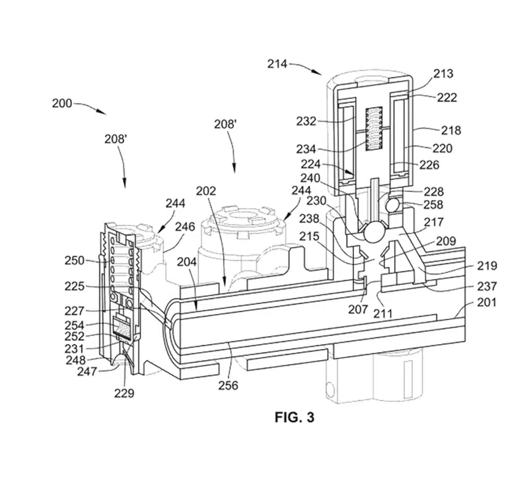
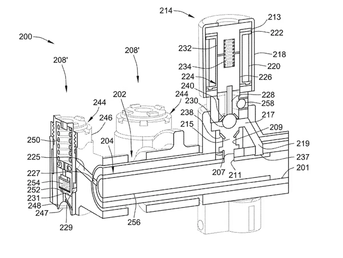
The valvetrain control system’s oil flow gallery routes oil from a feed passage in the cylinder head, into and through the rocker shaft and an insert sleeve within the rocker shaft, to an oil control valve (OCV) that is mounted onto a manifold that circumscribes the rocker shaft. The OCV is selectively activated to transmit oil to a worm track that is recessed into the exterior of the insert sleeve; the worm track feeds oil through a delivery port in the rocker shaft to a spring lock deactivation (DEAC) unit that is integrated into a pushrod mating end of the rocker arm.
Pressurizing the spring lock deactivation unit operatively disengages the rocker arm from the pushrod and thereby prevents the transmission of motion/load from the pushrod to the rocker arm; doing so deactivates the rocker arm and an intake/exhaust valve mated with that rocker.
To regulate the flow of oil through the rocker shaft, an outer-diameter (OD) surface of the insert sleeve may sit flush against and seal to an inner-diameter (ID) surface of the rocker shaft.
Switching oil may pass from the pressurized oil bore in the rocker shaft through open longitudinal ends of the insert sleeve; an oil feed port in the circumferential wall of the insert sleeve directs oil into an inlet port of the OCV. When activated, the OCV transmits oil flow from the OCV inlet port to an OCV control port; this control port redirects oil flow, e.g., via a control port passage in the OCV manifold, through a sleeve track pocket to a worm track in the sleeve.
The worm track delivers oil flow through an inlet channel in the rocker arm to the spring lock unit. The OCV includes a pressure-regulating port and a floating check valve that allows a minimum “priming” pressure to be maintained in the control gallery. This priming pressure is sufficient to enable fast switching of the VDV system, but low enough to ensure the VDV system does not inadvertently deactivate the rocker arms when it is not required.
What’s the benefit?
TLDR; less parts and less oil pulled from the engine should make the system more reliable.
Attendant benefits for at least some of the disclosed concepts may include a simplified and reduced cost VVL system that routes switching oil through the rocker shafts to the rocker arm spring lock units.
Using this routing arrangement allows for minimal changes to existing engine architecture while eliminating superfluous hoses, seals, valving, etc.
Other attendant benefits may include a VVL system that minimizes the amount of oil pulled from the existing engine oiling system while still providing the necessary oil and pressure to actuate the cylinder deactivation system and maintaining oil feed to the pushrod-to-rocker arm interface and rocker arm-rocker shaft interface.
Example of how it will work
TLDR; the rocker shaft will use hydraulic fluid to operate a spring that will cause it to open and close. When it operates, the rocker arms will move and operate pushrods to open and close intake and exhaust ports.
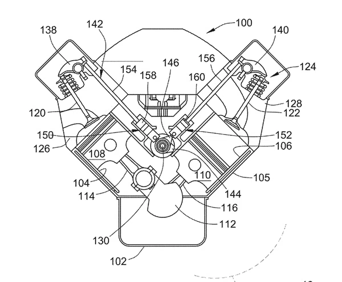
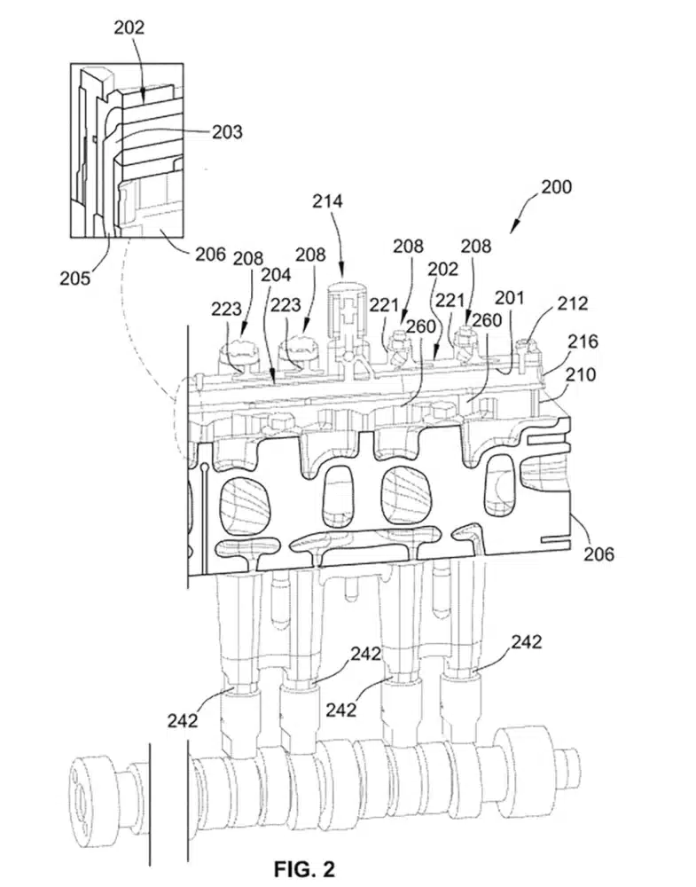
In an example, there is presented a valvetrain control system for an engine assembly, which has multiple cylinders, intake and exhaust valves for opening and closing intake and exhaust port to each cylinder, a camshaft rotatably attached proximate the valves, and multiple pushrods (e.g., with pushrod lifters) each seated on a respective cam of the camshaft. The valvetrain control system includes a rocker shaft that attaches to the engine assembly and includes an internal shaft bore for receiving hydraulic fluid. An oil control valve unit attaches to the rocker shaft and fluidly couples to the internal shaft bore to receive there from a portion of the hydraulic fluid. Multiple rocker arms pivotably mount onto the rocker shaft; one end of each rocker arm mates with a respective pushrod while the opposite end of the rocker arm mates with a respective valve. A subset of the rocker arms each includes a hydraulically actuated spring lock unit that is mounted to, integrally formed with, or otherwise attached to the pushrod end of the rocker arm. Each spring lock unit attaches its rocker arm to the pushrod and fluidly couples to the OCV unit. Receipt of hydraulic fluid from the OCV unit causes the spring lock unit to drivingly disengage the rocker arm from the pushrod. An insert sleeve is mounted inside the rocker shaft’s internal bore to receive hydraulic fluid from the rocker shaft. The insert sleeve includes a feed port that transmits hydraulic fluid from the rocker shaft and insert sleeve to an OCV inlet port of the OCV unit, and a feed pocket that transmits hydraulic fluid from an OCV outlet port of the OCV unit to each spring lock unit.
Other Options and Aspects of the Design
TLDR; The design can be altered to fit a variety of different engine designs.
For any of the disclosed VDV systems, vehicles, and methods, the insert sleeve may have an elongated and hollow sleeve body, such as a right-circular cylinder fabricated from carbon steel.
In this instance, the feed port is a through-hole that extends through a sidewall of the sleeve body, whereas the feed pocket is an elongated channel recessed into the outer surface of the sleeve body.
The insert sleeve may also include an elongated and rectilinear worm track that is recessed into the outer surface of the sleeve body, fluidly coupled to the feed pocket, and extends longitudinally along the length of the insert sleeve.
As another option, the rocker arm may include an inlet channel that fluidly couples to a feed orifice, which extends through a circumferential wall of the rocker shaft. In this instance, the worm track fluidly couples the inlet channel and feed orifice to the feed pocket and OCV outlet port to transmit hydraulic fluid from the OCV to the spring lock unit. It may be desirable that the insert sleeve be press-fit, slip-fit or transition-fit into the rocker shaft such that the sleeve’s outer surface sits flush against and thereby seals to the rocker shaft’s inner surface.
Moreover, the insert sleeve may be cast and precision machined as a single-piece cylindrical structure formed, in whole or in part, from a metallic material or a rigid polymeric material.
For any of the disclosed VDV systems, vehicles, and methods, the OCV unit may include a protective valve housing with an inlet chamber, a control duct, and a check valve. The inlet chamber is fluidly coupled to the OCV inlet port, the control duct is fluidly coupled to the OCV outlet port, and the check valve is interposed between the inlet chamber and control duct.
The OCV unit is selectively switchable (e.g., via command signal from the ECM) to transition between an OFF state and an ON state. When in the OFF state, the check valve restricts hydraulic fluid flow from the OCV inlet port to the OCV outlet port.
When in the ON state, the check valve permits unrestricted hydraulic fluid flow from the OCV inlet port to the OCV outlet port. The check valve may include a solenoid-controlled check ball that seats against a valve seat.
When the OCV unit is in the OFF state, the check ball may be at least partially unseated from the valve seat to maintain a predefined priming pressure in the hydraulic fluid.
The OCV unit may also include a pressure relief valve that regulates the priming pressure when the OCV unit is OFF (e.g., ensure the priming pressure does not reach a valve deactivation pressure).
For any of the disclosed VDV systems, vehicles, and methods, the spring lock unit may include an outer lock housing, a pushrod piston that is translatable within the lock housing, and a spring-biased lock pin that locks the pushrod piston to the lock housing. The pushrod piston may include a pushrod seat that seats therein one end of the pushrod. A lost-motion return spring may be disposed within the lock housing to bias the pushrod piston towards the pushrod.
Hydraulic fluid fed from the OCV unit through the insert sleeve and into the lock housing, e.g., upon reaching the valve deactivation pressure, disengages the spring-biased lock pin to thereby unlock the pushrod piston from the lock housing, thereby drivingly disengaging the pushrod from the rocker arm.
Disengaging the spring-biased lock pin enables the pushrod piston and the pushrod to translate against a return spring in the lock housing. The lock housing may be integrally formed with the pushrod end of the rocker arm as a single-piece structure.
For any of the disclosed VDV systems, vehicles, and methods, each OCV unit may physically mount directly onto and circumscribe the OD surface of the rocker shaft (e.g., eliminating superfluous plumbing between the OCV and rocker shaft).
In the same vein, each rocker arm and spring lock unit may physically mount directly onto and circumscribe the OD surface of the rocker shaft (e.g., eliminating superfluous plumbing between the OCV and rocker arm).
One end of the rocker shaft may include an inlet port that extends through a sidewall of the rocker shaft and fluidly couples to and receives hydraulic fluid from a feed passage in the engine’s cylinder head.
The rocker shaft may also include a shaft outlet port that extends through a sidewall of the rocker shaft and fluidly couples to the shaft inlet port via the internal shaft bore. The rocker shaft’s outlet port aligns with and directly fluidly couples to the OCV unit’s inlet port and the insert sleeve’s feed port.
Our take

The current dynamic fuel management system has been a center of attention for many years in often a negative light. Critics point to it as being the reason for many of GM’s engine failure woes going back to the 2010s.
They claim the system starves the engine of oil, causes lifter failure through excessively calling on them to turn on and off and it doesn’t really provide any measurable MPG gain. These concerns have also led to owners buying aftermarket kits to turn off cylinder deactivation systems and/or have mechanics do mechanical deletes.
If this new system uses less oil, simplifies things with less parts and overall is more reliable, this should help reduce the concerns many owners have and reduce the need for them to buy kits or pay mechanics. The key word there is “should.”
With the 2027 Chevy Silverado 1500 and GMC Sierra 1500 redesign coming in the fall of 2026 and the fact GM is investing $888 million in the next-generation V8 engines, the timing seems right for this technology to make its debut in those trucks.


2 replies
Loading new replies...
Administrator
Well-known member
Administrator
Join the full discussion at the Forum Pickuptrucktalk →